ATOMIC CLOCK
The principle of operation of an atomic clock is not based on
nuclear physics, but rather on
atomic physics and using the
microwave signal that
electrons in atoms emit when they change
energy levels. Early atomic clocks were based on
masers at room temperature. Currently, the most accurate atomic clocks first cool the atoms to near
absolute zero temperature by slowing them with lasers and probing them in
atomic fountains in a microwave-filled cavity. An example of this is the
NIST-F1 atomic clock, the U.S. national primary time and frequency standard.
The accuracy of an atomic clock depends on the temperature of the sample atoms—colder atoms move much more slowly, allowing longer probe times, as well as having reduced collision rates—and on the frequency and intrinsic width of the electronic transition. Higher frequencies and narrow lines increase the precision.
National standards agencies maintain an accuracy of 10
−9 seconds per day (approximately 1 part in 10
14), and a precision set by the radio transmitter
pumping the maser. These clocks collectively define a continuous and stable time scale,
International Atomic Time (TAI). For civil time, another time scale is disseminated,
Coordinated Universal Time (UTC). UTC is derived from TAI, but approximately synchronized, by using
leap seconds, to
UT1, which is based on actual rotations of the earth with respect to the
solar time.
[edit]History
The idea of using atomic transitions to measure time was first suggested by
Lord Kelvin in 1879.
[3] Magnetic resonance, developed in the 1930s by
Isidor Rabi, became the practical method for doing this.
[4] In 1945, Rabi first publicly suggested that atomic beam magnetic resonance might be used as the basis of a clock.
[5] The first atomic clock was an
ammonia maser device built in 1949 at the U.S.
National Bureau of Standards (NBS, now
NIST). It was less accurate than existing
quartz clocks, but served to demonstrate the concept.
[6] The first accurate atomic clock, a
caesium standard based on a certain transition of the
caesium-133 atom, was built by
Louis Essen in 1955 at the
National Physical Laboratory in the UK.
[7] Calibration of the caesium standard atomic clock was carried out by the use of the astronomical time scale
ephemeris time (ET).
[8] This led to the internationally agreed definition of the latest
SI second being based on atomic time. Equality of the ET second with the (atomic clock)
SI second has been verified to within 1 part in 10
10.
[9] The SI second thus inherits the effect of decisions by the original designers of the
ephemeris time scale, determining the length of the ET second.

May 2009-
JILA's strontium optical atomic clock is based on neutral atoms. Shining a blue laser onto ultracold strontium atoms in an optical trap tests how efficiently a previous burst of light from a red laser has boosted the atoms to an excited state. Only those atoms that remain in the lower energy state respond to the blue laser, causing the fluorescence seen here.
[10]
Since the beginning of development in the 1950s, atomic clocks have been based on the hyperfine (microwave) transitions in
hydrogen-1,
caesium-133, and
rubidium-87. The first commercial atomic clock was the
Atomichron, manufactured by the
National Company. More than 50 were sold between 1956 and 1960. This bulky and expensive instrument was subsequently replaced by much smaller rack-mountable devices, such as the
Hewlett-Packard model 5060 caesium frequency standard, released in 1964.
[4]
In the late 1990s four factors contributed to major advances in clocks:
[11]
In August 2004,
NIST scientists demonstrated a chip-scaled atomic clock.
[12] According to the researchers, the clock was believed to be one-hundredth the size of any other. It was also claimed that it requires just 75
mW, making it suitable for battery-driven applications. This device could conceivably become a consumer product.
[edit]Mechanism
Since 1967, the
International System of Units (SI) has defined the
second as the duration of
9192631770cycles of radiation corresponding to the transition between two energy levels of the caesium-133 atom.
[13]
This definition makes the caesium oscillator the primary standard for time and frequency measurements, called the
caesium standard. Other physical quantities, e.g., the
volt and the
metre, rely on the definition of the second in their own definitions.
[14]
The actual time-reference of an atomic clock consists of an electronic oscillator operating at microwave frequency. The oscillator is arranged so that its frequency-determining components include an element that can be controlled by a feedback signal. The feedback signal keeps the oscillator tuned in
resonance with the frequency of the electronic transition of caesium or rubidium.
The core of the atomic clock is a tunable
microwave cavity containing the gas. In a
hydrogen maser clock the gas emits
microwaves (the gas
mases) on a
hyperfine transition, the field in the cavity oscillates, and the cavity is tuned for maximum microwave amplitude. Alternatively, in a caesium or rubidium clock, the beam or gas absorbs microwaves and the cavity contains an electronic amplifier to make it oscillate. For both types the atoms in the gas are prepared in one electronic state prior to filling them into the cavity. For the second type the number of atoms which change electronic state is detected and the cavity is tuned for a maximum of detected state changes.
Most of the complexity of the clock lies in this adjustment process. The adjustment tries to correct for unwanted side-effects, such as frequencies from other electron transitions, temperature changes, and the spreading in frequencies caused by ensemble effects. One way of doing this is to sweep the microwave oscillator's frequency across a narrow range to generate a modulated signal at the detector. The detector's signal can then be
demodulated to apply feedback to control long-term drift in the radio frequency. In this way, the quantum-mechanical properties of the atomic transition frequency of the caesium can be used to tune the microwave oscillator to the same frequency, except for a small amount of experimental error. When a clock is first turned on, it takes a while for the oscillator to stabilize. In practice, the feedback and monitoring mechanism is much more complex than described above.

Historical accuracy of atomic clocks from
NIST
A number of other atomic clock schemes are in use for other purposes.
Rubidium standard clocks are prized for their low cost, small size (commercial standards are as small as 400 cm
3) and short-term stability. They are used in many commercial, portable and aerospace applications. Hydrogen masers (often manufactured in Russia) have superior short-term stability compared to other standards, but lower long-term accuracy.
Often, one standard is used to fix another. For example, some commercial applications use a rubidium standard periodically corrected by a
global positioning system receiver. This achieves excellent short-term accuracy, with long-term accuracy equal to (and traceable to) the U.S. national time standards.
The lifetime of a standard is an important practical issue. Modern rubidium standard tubes last more than ten years, and can cost as little as US$50.
[citation needed] Caesium reference tubes suitable for national standards currently last about seven years and cost about US$35,000. The long-term stability of hydrogen maser standards decreases because of changes in the cavity's properties over time.
[edit]Physics package realizations
There exists a number of methods of utilizing the hyperfine splitting. These methods have their benefits and draw-backs and have influenced the development of commercial devices and laboratory standards. By tradition the hardware which is used to probe the atoms is called the physics package.
[edit]Atomic beam standard
The atomic beam standard is a direct extension of the
Stern-Gerlach atomic splitting experiment. The atoms of choice are heated in an oven to create gas, which is collimated into a beam. This beam passes through a state-selector magnet A, where atoms of the wrong state are separated out from the beam. The beam is exposed to an RF field at or near the transition. The beam then passes through a space before it is again exposed to the RF field. The RF field and a static homogeneous magnetic field from the C-field coil will change the state of the atoms. After the second RF field exposure the atomic beam passes through a second state selector magnet B, where the atom state being selected out of the beam at the A magnet is being selected. This way, the detected amount of atoms will relate to the ability to match the atomic transition. After the second state-selector a mass-spectrometer using an ionizer will detect the rate of atoms being received.
Modern variants of this beam mechanism use optical pumping to transition all atoms to the same state rather than dumping half the atoms. Optical detection using scintillation can also be used.
The most common isotope for beam devices is
caesium (
133Cs), but
rubidium (
87Rb) and
thallium (
205Tl) are examples of others used in early research.
The frequency errors can be made very small for a beam device, or predicted (such as the magnetic field pull of the C-coil) in such a way that a high degree of repeatability and stability can be achieved. This is why an atomic beam can be used as a primary standard.
[edit]Atomic gas cell standard
The atomic gas cell standard builds on a confined reference isotope (often an alkali metal such as Rubidium (87Rb)) inside an RF cavity. The atoms are excited to a common state using optical pumping; when the applied RF field is swept over the hyperfine spectrum, the gas will absorb the pumping light, and a photodetector provides the response. The absorption peak steers the fly-wheel oscillator.
A typical rubidium gas-cell uses a rubidium (87Rb) lamp heated to 108-110 degrees Celsius, and an RF field to excite it to produce light, where the D1 and D2 lines are the significant wavelengths. An85Rb cell filters out the D1 line so that only the D2 line pumps the 87Rb gas cell in the RF cavity.
Among the significant frequency pulling mechanisms inherent to the gas cell are wall-shift, buffer-gas shift, cavity-shift and light-shift. The wall-shift occurs as the gas bumps into the wall of the glass container. Wall-shift can be reduced by wall coating and compensation by buffer gas. The buffer gas shift comes from the reference atoms which bounce into buffer gas atoms such as neon and argon; these shifts can be both positive and negative. The cavity shift comes from the RF cavity, which can deform the resonance amplitude response; this depends upon cavity center frequency and resonator Q-value. Light-shift is an effect where frequency is pulled differently depending on the light intensity, which often is modulated by the temperature shift of the rubidium lamp and filter cell.
There are thus many factors in which temperature and aging can shift frequency over time, and this is why a gas cell standard is unfit for a primary standard, but can become a very inexpensive, low-power and small-size solution for a secondary standard or where better stability compared to crystal oscillators is needed, but not the full performance of a caesium beam standard. The rubidium gas standards have seen use in telecommunications systems and portable instruments.
[edit]Active maser standard
The active maser standard is a development from the atomic beam standard in which the observation time was incremented by using a bounce-box. By controlling the beam intensity spontaneous emission will provide sufficient energy to provide a continuous oscillation, which is being tapped and used as a reference for a fly-wheel oscillator.
The active maser is sensitive to wall-shift and cavity pulling. The wall-shift is mitigated by using PTFE coating (or other suitable coating) to reduce the effect. The cavity pulling effect can be reduced by automatic cavity tuning. In addition the magnetic field pulls the frequency.
While not being long-term stable as caesium beams, it remains one of the most stable sources available. The inherent pulling effects makes repeatability troublesome and does prohibits its use as being primary standard, but it makes an excellent secondary standard. It is used as low-noise fly-wheel standard for caesium beam standards.
[edit]Fountain standard
The fountain standard is a development from the beam standard where the beam has been folded back to itself such that the first and second RF field becomes the same RF cavity. A ball of atoms is laser cooled, which reduces black body temperature shifts. Phase errors between RF cavities are essentially removed. The length of the beam is longer than many beams, but the speed is also much slower such that the observation time becomes significantly longer and hence a higher Q value is achieved in the Ramsey fringes.
Caesium fountains has been implemented in many laboratories, but rubidium has even greater ability to provide stability in the fountain configuration.
[edit]Ion trap standard
The ion trap standard is a set of different approaches, but their common property is that an ionized atom is confined in a electrostatic field and cooled down. The hyperfine region of the available electron is then being tracked similar to that of a gas cell standard.
Ion traps have been used for numerous ions, where mercury 199Hg+ was an early candidate.
[edit]Power consumption
The power consumption of atomic clocks varies with their size.
[citation needed] One chip scale atomic clocks require power less than 75
mW; NIST-F1 uses power orders of magnitude greater.
[citation needed]
[edit]Research
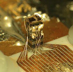
Chip-scale atomic clock unveiled by
NIST
Most research focuses on the often conflicting goals of making the clocks smaller, cheaper, more accurate, and more reliable.
New technologies, such as femtosecond frequency combs, optical lattices and
quantum information, have enabled prototypes of next generation atomic clocks. These clocks are based on optical rather than microwave transitions. A major obstacle to developing an optical clock is the difficulty of directly measuring optical frequencies. This problem has been solved with the development of self-referenced mode-locked lasers, commonly referred to as femtosecond
frequency combs. Before the demonstration of the frequency comb in 2000,
terahertz techniques were needed to bridge the gap between radio and optical frequencies, and the systems for doing so were cumbersome and complicated. With the refinement of the frequency comb these measurements have become much more accessible and numerous optical clock systems are now being developed around the world.
Like in the radio range, absorption spectroscopy is used to stabilize an oscillator—in this case a laser. When the optical frequency is divided down into a countable radio frequency using a
femtosecond comb, the
bandwidth of the
phase noise is also divided by that factor. Although the bandwidth of laser phase noise is generally greater than stable microwave sources, after division it is less.
The two primary systems under consideration for use in optical frequency standards are single ions isolated in an ion trap and neutral atoms trapped in an optical lattice.
[15] These two techniques allow the atoms or ions to be highly isolated from external perturbations, thus producing an extremely stable frequency reference.
Optical clocks have already achieved better stability and lower systematic uncertainty than the best microwave clocks.
[15] This puts them in a position to replace the current standard for time, the caesium fountain clock.
[edit]Quantum clocks
In March 2008, physicists at
NIST described a
quantum logic clock based on individual
ions of
beryllium and
aluminium. This clock was compared to NIST's
mercury ion clock. These were the most accurate clocks that had been constructed, with neither clock gaining nor losing time at a rate that would exceed a second in over a billion years.
[16] In February 2010, NIST physicists described a second, enhanced version of the quantum logic clock based on individual
ions of
magnesium and
aluminium. Considered the world's most precise clock, it offers more than twice the precision of the original.
[17] [18]
[edit]Evaluated accuracy
In 2011, the NPL-CsF2 cesium fountain clock operated by the
National Physical Laboratory (NPL), which serves as the United Kingdom primary
time and frequency standard, was improved regarding the two largest sources of measurement uncertainties — distributed cavity phase and microwave lensing frequency shifts. As of 2011 this resulted in an evaluated frequency uncertainty reduction from 4.1 x 10
-16[19] to 2.3 x 10
-16 — the lowest value for any primary national standard so far. At this frequency uncertainty the NPL-CsF2 is expected to neither gain nor lose a second in more than 138 million years.
[20][21][22]
[edit]Applications
The development of atomic clocks has led to many scientific and technological advances such as a worldwide system of precise position measurement (Global Positioning System), and applications in the
Internet, which depend critically on frequency and time standards. Atomic clocks are installed at sites of
time signal radio transmitters. They are used at some long wave and medium wave broadcasting stations to deliver a very precise carrier frequency.
[citation needed] Atomic clocks are used in many scientific disciplines, such as for long-baseline
interferometry in
radioastronomy.
[23]
[edit]Global Positioning System
The
Global Positioning System (GPS) provides very accurate timing and frequency signals. A GPS receiver works by measuring the relative time delay of signals from a minimum of four, but usually more GPS satellites, each of which has four onboard caesium or rubidium atomic clocks. The relative times are mathematically transformed into three absolute spatial coordinates and one absolute time coordinate. The time is accurate to within about 50 nanoseconds. However, inexpensive GPS receivers may not assign a high priority to updating the display, so the displayed time may differ perceptibly from the internal time. Precision time references that use GPS are marketed for use in computer networks, laboratories, and cellular communications networks, and do maintain accuracy to within about
50ns.
[edit]Time signal radio transmitters
A
radio clock is a clock that automatically synchronizes itself by means of government radio
time signals received by a
radio receiver. Many retailers market radio clocks inaccurately as atomic clocks; although the radio signals they receive originate from atomic clocks, they are not atomic clocks themselves. They are inexpensive time-keeping devices with an accuracy of about a second. Instrument grade time receivers provide higher accuracy. Such devices incur a transit delay of approximately 1
ms for every 300 kilometres (186 mi) of distance from the
radio transmitter. Many governments operate transmitters for time-keeping purposes.


 Needless to say, when a cell phone company wants a small GPS tracking chip to install in their cell phone they are going to consider the folks at Rankon.


